1. Summary
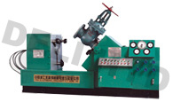
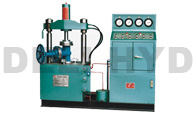
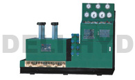
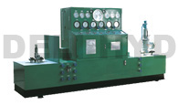
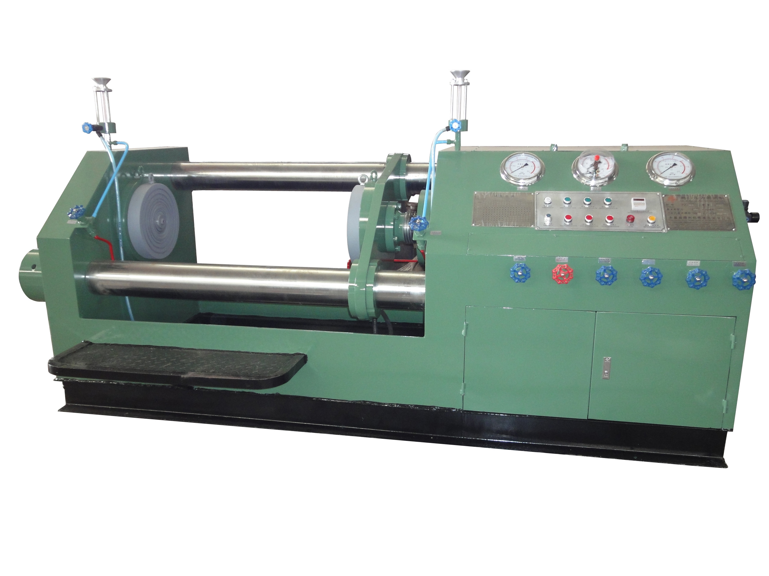
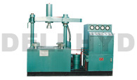
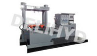
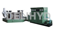
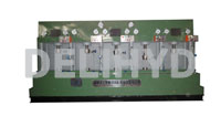
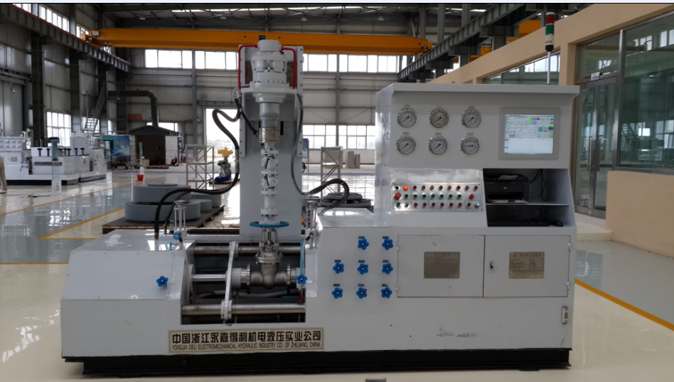
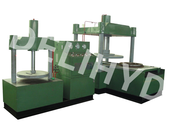
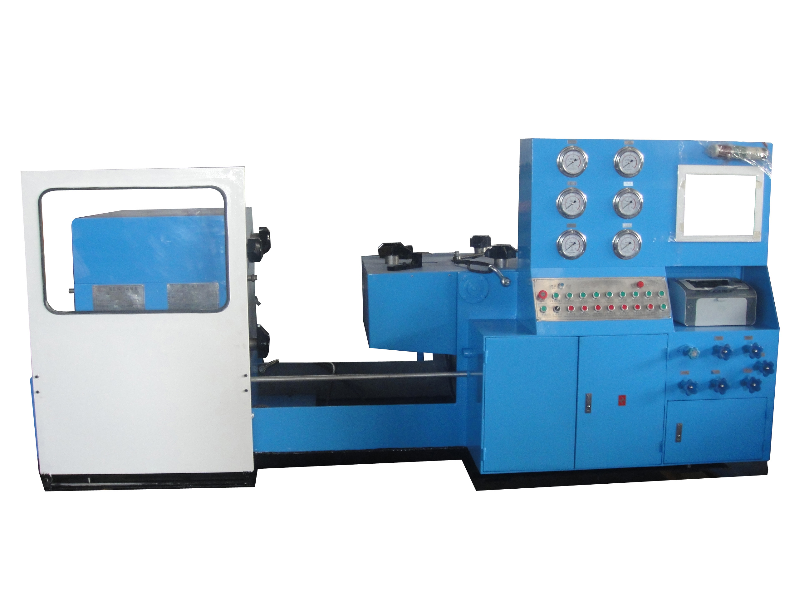
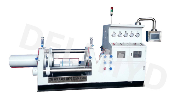
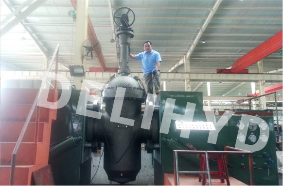
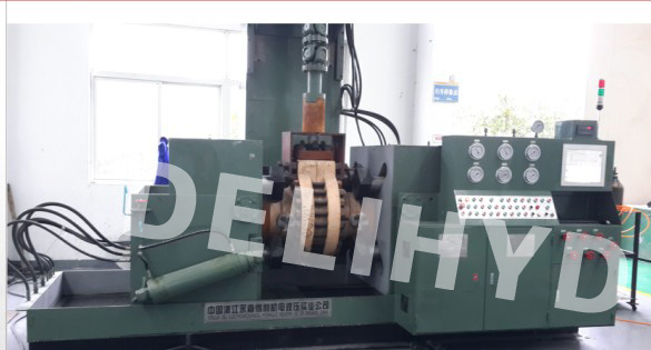
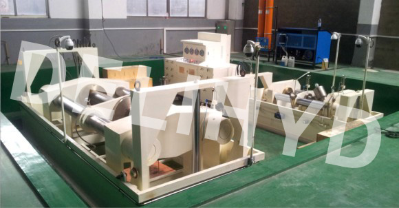
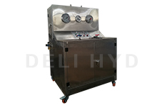
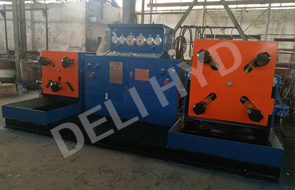
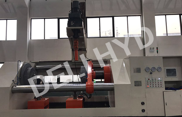
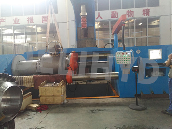
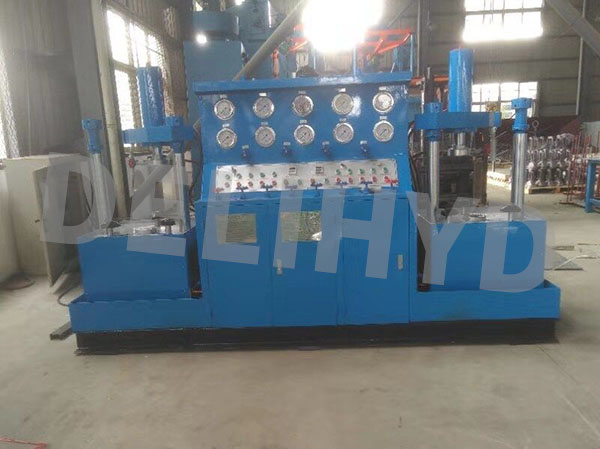
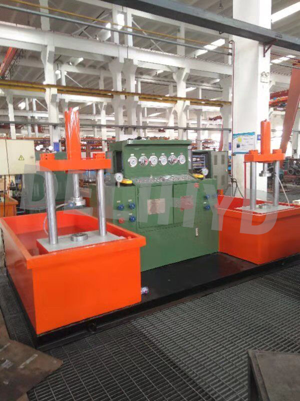
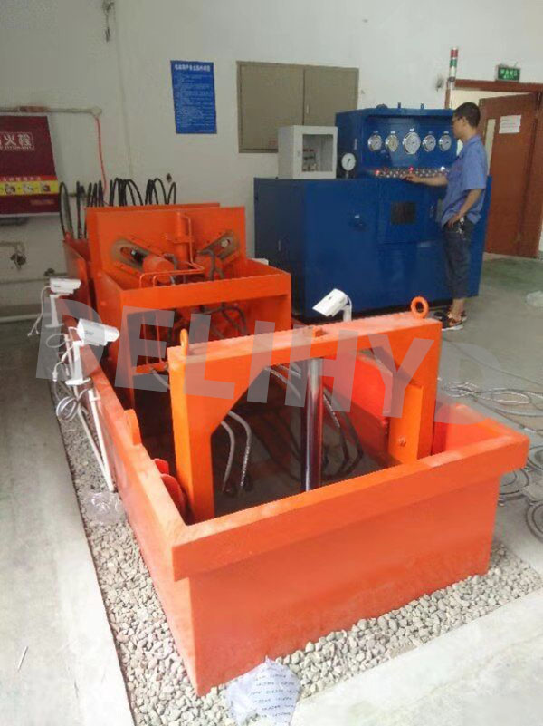
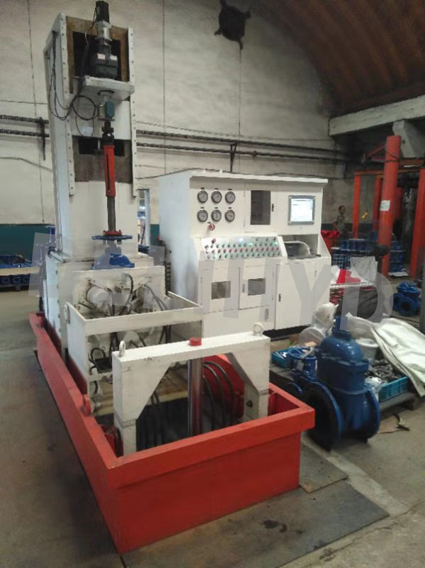
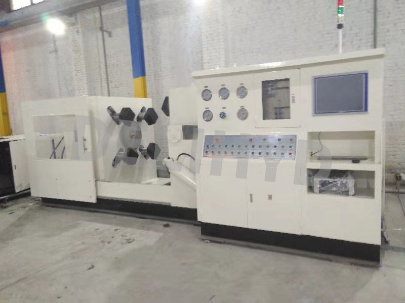
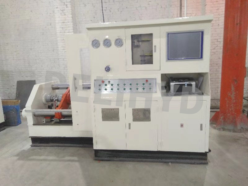
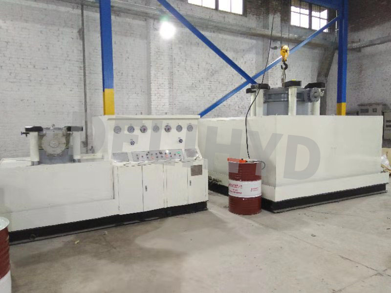
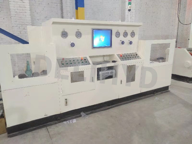
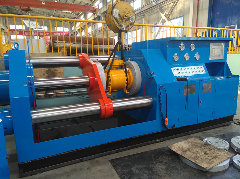
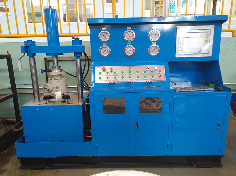
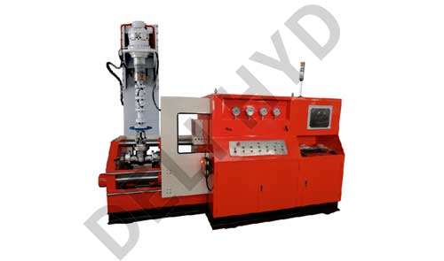
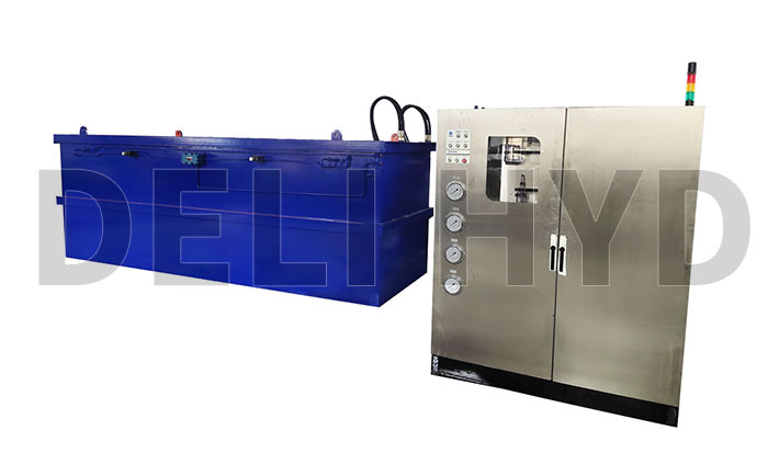
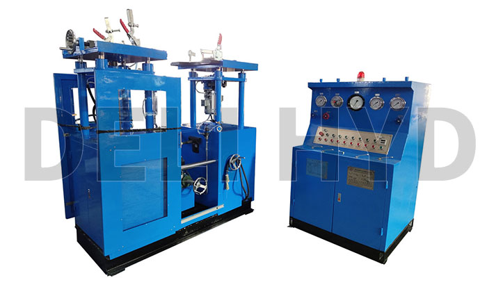
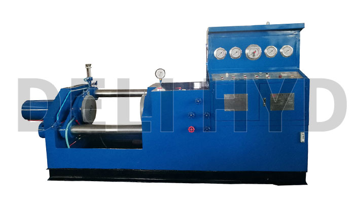
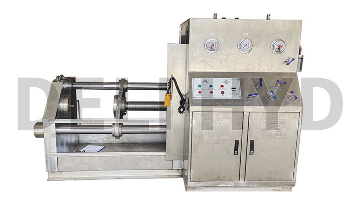
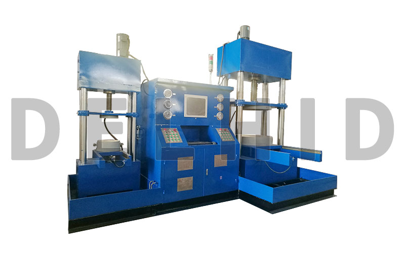
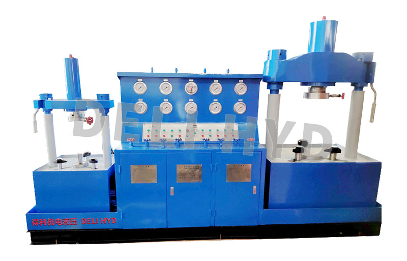
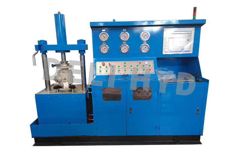
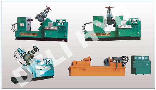
The hydraulic valve test bench of model YFS-Z is specially applied to test all kinds of flanged valves,such as gate valves, ball valves, globe valves, check valves etc. The test bench is effectively composed of four parts, that is, mechanical system, hydraulic system, electric system and testing medium circulating system. The entire process of the loading and clamping of the valve to be tested is completely controlled by electric components and hydraulic components. The testing medium can be water, gas or oil. And the maximum testing pressure of shell test with liquid (water) is 48Mpa. Test benches of this model are of the following features,such as rational and compact in configuration, flawless in function, steady and reliable in performance,high in degree of automation, advanced in technics and so on.
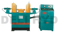
What is important, the test benches of this model have no effect of external force upon the valve body,because the clamping jaw clamp directly on the flange of the valve. One side of the bench can be moved,thus the testing won′t be restricted by the structural length of the valve to be tested. When testing valves, clamp the flange on the both sides of the valve to be tested, pressurize to the necessary pressure of the medium′s intensity test and perform intensity test of the valve body, valve cover and middle flange. And the other side of the bench can be reversed by 90 degrees to perform leakage test and airtightness test. The testing methods of the test bench conform completely to the requirements of the following standards,GB/T13927-92“ Pressure testing of general valves”JB/T9092-99“ Valve inspection and testing”and the American standard of API598 etc.
2. Technical Parameters
Model&
Specification |
Type |
TestingRange |
Spacing between Two Working Plates (mm) |
Stroke & Lift Range of Clamping Jaw (mm) |
Diameter & Quantity of Clamping Oil Cylinder |
Max.Clamping Force (t) |
Electromotor of Oil Pump(6 Poles) |
Outline Dimensions (L×W×H) |
| YFS-Z100 |
Unitary |
DN15-100 |
170-700 |
125×52 |
φ 80×3 |
30 |
2.2KW |
1080×2300×1050 |
| YFS-Z200 |
Unitary |
DN50-200 |
250-900 |
156×62 |
φ 100×3 |
50 |
2.2KW |
1240×2700×1230 |
| YFS-Z300 |
Unitary |
DN80-300 |
300-1150 |
200×75 |
φ 140×3 |
90 |
3.0KW |
1360×3050×1300 |
| YFS-Z400 |
Unitary |
DN150-400 |
400-1400 |
200×80 |
φ 160×3 |
120 |
3.0KW |
1580×3350×1400 |
| YFS-Z500 |
Unitary |
DN250-500 |
450-1500 |
225×95 |
φ 160×4 |
160 |
5.5KW |
1620×3750×1550 |
| YFS-Z600 |
Unitary |
DN300-600 |
450-1500 |
250×95 |
φ 200×4 |
250 |
5.5KW |
1700×3900×1650 |
| YFS-Z800 |
Separate |
DN400-800 |
550-1650 |
320×105 |
φ 250×4 |
350 |
5.5KW |
2900×5000×1950 |
| YFS-Z1000 |
Separate |
DN500-1000 |
650-1800 |
350×105 |
φ 220×6 |
450 |
5.5KW |
3100×5300×2000 |
3. Pressure Check List of Clamping Oil Cylinder
Model YFS-Z100
| Nominal Diameter |
Nominal Pressure MPa/class |
| 1.6 |
2.5 |
4.0 |
6.4 |
10.0 |
16.0 |
20.0 |
25.0 |
32.0 |
|
150 |
300 |
400 |
600 |
900 |
|
1500 |
|
|
Pressure of Hydraulic Station |
| in |
mm |
PN |
PS |
PN |
PS |
PN |
PS |
PN |
PS |
PN |
PS |
PN |
PS |
PN |
PS |
PN |
PS |
PN |
PS |
| 1/2″ |
DN15 |
● |
● |
● |
● |
● |
● |
● |
● |
● |
● |
● |
● |
● |
● |
● |
● |
● |
● |
| 3/4″ |
DN20 |
● |
● |
● |
● |
● |
● |
● |
● |
● |
● |
● |
● |
● |
● |
● |
● |
● |
● |
| 1″ |
DN25 |
● |
● |
● |
● |
● |
● |
● |
● |
● |
● |
● |
● |
● |
● |
● |
● |
● |
● |
| 11/4″ |
DN32 |
● |
● |
● |
● |
● |
● |
● |
● |
● |
● |
● |
● |
● |
● |
● |
● |
● |
● |
| 11/2″ |
DN40 |
● |
● |
● |
● |
● |
● |
● |
● |
● |
● |
● |
● |
● |
● |
● |
● |
● |
● |
| 2 ″ |
DN50 |
● |
● |
● |
● |
● |
● |
● |
● |
● |
● |
● |
● |
● |
● |
● |
● |
● |
● |
| 21/2″ |
DN65 |
● |
● |
● |
● |
● |
● |
● |
● |
● |
● |
● |
● |
● |
● |
● |
● |
|
|
| 3 ″ |
DN80 |
● |
● |
● |
● |
● |
● |
● |
● |
● |
● |
● |
● |
● |
● |
|
|
|
|
| 4″ |
DN100 |
● |
● |
● |
● |
● |
● |
● |
● |
● |
● |
|
|
|
|
|
|
|
|
Model YFS-Z200
| Nominal Diameter |
Nominal Pressure MPa/class |
| 1.6 |
2.5 |
4.0 |
6.4 |
10.0 |
16.0 |
20.0 |
25.0 |
32.0 |
|
150 |
300 |
400 |
600 |
900 |
|
1500 |
|
|
Pressure of Hydraulic Station |
| in |
mm |
PN |
PS |
PN |
PS |
PN |
PS |
PN |
PS |
PN |
PS |
PN |
PS |
PN |
PS |
PN |
PS |
PN |
PS |
| 2″ |
DN50 |
● |
● |
● |
● |
● |
● |
● |
● |
● |
● |
● |
● |
● |
● |
● |
● |
● |
● |
| 21/2 ″ |
DN65 |
● |
● |
● |
● |
● |
● |
● |
● |
● |
● |
● |
● |
● |
● |
● |
● |
● |
● |
| 3″ |
DN80 |
● |
● |
● |
● |
● |
● |
● |
● |
● |
● |
● |
● |
● |
● |
● |
● |
● |
● |
| 4 ″ |
DN100 |
● |
● |
● |
● |
● |
● |
● |
● |
● |
● |
● |
● |
● |
● |
● |
● |
|
|
| 5″ |
DN125 |
● |
● |
● |
● |
● |
● |
● |
● |
● |
● |
● |
● |
|
|
|
|
|
|
| 6″ |
DN150 |
● |
● |
● |
● |
● |
● |
● |
● |
● |
● |
|
|
|
|
|
|
|
|
| 8″ |
DN200 |
● |
● |
● |
● |
● |
● |
● |
● |
|
|
|
|
|
|
|
|
|
|
PN-denotes the pressure of the oil cylinder when performing seat test;PS-denotes the pressure of the oil cylinder when performing shell test
Model YFS-Z300
|
Nominal Diameter |
Nominal Pressure MPa/class |
|
1.6 |
2.5 |
4.0 |
6.4 |
10.0 |
160 |
20.0 |
250 |
320 |
|
150 |
300 |
400 |
600 |
900 |
|
1500 |
|
|
Pressure of Hydraulic Station |
|
in |
mm |
PN |
PS |
PN |
PS |
PN |
PS |
PN |
PS |
PN |
PS |
PN |
PS |
PN |
PS |
PN |
PS |
PN |
PS |
|
3″ |
DN80 |
● |
● |
● |
● |
● |
● |
● |
● |
● |
● |
● |
● |
● |
● |
● |
● |
● |
● |
|
4″ |
DN100 |
● |
● |
● |
● |
● |
● |
● |
● |
● |
● |
● |
● |
● |
● |
● |
● |
● |
● |
|
5″ |
0N125 |
● |
● |
● |
● |
● |
● |
● |
● |
● |
● |
● |
● |
● |
● |
● |
● |
● |
● |
|
6″ |
DN150 |
● |
● |
● |
● |
● |
● |
● |
● |
● |
● |
● |
● |
● |
● |
● |
● |
|
|
|
8″ |
DN200 |
● |
● |
● |
● |
● |
● |
● |
● |
● |
● |
● |
● |
|
|
|
|
|
|
|
10″ |
DN250 |
● |
● |
● |
● |
● |
● |
● |
● |
● |
● |
|
|
|
|
|
|
|
|
|
12″ |
DN300 |
● |
● |
● |
● |
● |
● |
● |
● |
|
|
|
|
|
|
|
|
|
|
Model YFS-Z400
|
Nominal Diameter |
Nominal Pressure MPa/class |
|
1.0 |
1.6 |
2.5 |
4.0 |
6.4 |
10.0 |
16.0 |
20.0 |
25.0 |
|
|
150 |
300 |
400 |
600 |
900 |
|
|
|
Pressure of Hydraulic Station |
|
in |
mm |
PN |
PS |
PN |
PS |
PN |
PS |
PN |
PS |
PN |
PS |
PN |
PS |
PN |
PS |
PN |
PS |
PN |
PS |
|
6″ |
DN150 |
● |
● |
● |
● |
● |
● |
● |
● |
● |
● |
● |
● |
● |
● |
● |
● |
|
|
|
8″ |
DN200 |
● |
● |
● |
● |
● |
● |
● |
● |
● |
● |
● |
● |
● |
● |
● |
● |
|
|
|
10″ |
DN250 |
● |
● |
● |
● |
● |
● |
● |
● |
● |
● |
● |
● |
|
|
|
|
|
|
|
12″ |
DN300 |
● |
● |
● |
● |
● |
● |
● |
● |
● |
● |
● |
● |
|
|
|
|
|
|
|
14″ |
DN350 |
● |
● |
● |
● |
● |
● |
● |
● |
● |
● |
|
|
|
|
|
|
|
|
|
16″ |
DN400 |
● |
● |
● |
● |
● |
● |
● |
● |
|
|
|
|
|
|
|
|
|
|
Model YFS-Z500
|
Nominal Diameter |
Nominal Pressure MPa/class |
|
1.0 |
1.6 |
2.5 |
4.0 |
6.4 |
10.0 |
16.0 |
20.0 |
25.0 |
|
|
150 |
300 |
400 |
600 |
900 |
|
|
|
Pressure of Hydraulic Station |
|
in |
mm |
PN |
PS |
PN |
PS |
PN |
PS |
PN |
PS |
PN |
PS |
PN |
PS |
PN |
PS |
PN |
PS |
PN |
PS |
|
10″ |
DN250 |
● |
● |
● |
● |
● |
● |
● |
● |
● |
● |
● |
● |
● |
● |
● |
● |
|
|
|
12″ |
DN300 |
● |
● |
● |
● |
● |
● |
● |
● |
● |
● |
● |
● |
|
|
|
|
|
|
|
14″ |
DN350 |
● |
● |
● |
● |
● |
● |
● |
● |
● |
● |
● |
● |
|
|
|
|
|
|
|
16″ |
DN400 |
● |
● |
● |
● |
● |
● |
● |
● |
● |
● |
|
|
|
|
|
|
|
|
|
18″ |
DN450 |
● |
● |
● |
● |
● |
● |
● |
● |
|
|
|
|
|
|
|
|
|
|
|
20″ |
DN500 |
● |
● |
● |
● |
● |
● |
● |
● |
|
|
|
|
|
|
|
|
|
|
Model YFS-Z600
|
Nominal Diameter |
Nominal Pressure MPa/class |
|
0.6 |
1.0 |
1.6 |
2.5 |
4.0 |
6.4 |
10.0 |
16.0 |
20.0 |
|
|
|
150 |
300 |
400 |
600 |
900 |
|
|
Pressure of Hydraulic Station |
|
in |
mm |
PN |
PS |
PN |
PS |
PN |
PS |
PN |
PS |
PN |
PS |
PN |
PS |
PN |
PS |
PN |
PS |
PN |
PS |
|
12″ |
DN300 |
● |
● |
● |
● |
● |
● |
● |
● |
● |
● |
● |
● |
● |
● |
● |
● |
|
|
|
14″ |
DN350 |
● |
● |
● |
● |
● |
● |
● |
● |
● |
● |
● |
● |
● |
● |
|
|
|
|
|
16″ |
DN400 |
● |
● |
● |
● |
● |
● |
● |
● |
● |
● |
● |
● |
● |
● |
|
|
|
|
|
18″ |
DN450 |
● |
● |
● |
● |
● |
● |
● |
● |
● |
● |
● |
● |
|
|
|
|
|
|
|
20″ |
DN500 |
● |
● |
● |
● |
● |
● |
● |
● |
● |
● |
● |
● |
|
|
|
|
|
|
|
24″ |
DN600 |
● |
● |
● |
● |
● |
● |
● |
● |
● |
● |
|
|
|
|
|
|
|
|
PN-denotes the pressure of the oil cylinder when performing seat test;PS-denotes the pressure of the oil cylinder when performing shell test
Model YFS-Z800
|
Nominal Diameter |
Nominal Pressure MPa/class |
| 0.6 |
1.0 |
1.6 |
2.5 |
4.0 |
6.4 |
10.0 |
16.0 |
20.0 |
|
|
|
150 |
300 |
400 |
600 |
900 |
|
|
Pressure of Hydraulic Station |
| in |
mm |
PN |
PS |
PN |
PS |
PN |
PS |
PN |
PS |
PN |
PS |
PN |
PS |
PN |
PS |
PN |
PS |
PN |
PS |
| 16″ |
DN400 |
● |
● |
● |
● |
● |
● |
● |
● |
● |
● |
● |
● |
● |
● |
|
|
|
|
| 18″ |
DN450 |
● |
● |
● |
● |
● |
● |
● |
● |
● |
● |
● |
● |
● |
● |
|
|
|
|
| 20″ |
DN500 |
● |
● |
● |
● |
● |
● |
● |
● |
● |
● |
● |
● |
|
|
|
|
|
|
| 24″ |
DN600 |
● |
● |
● |
● |
● |
● |
● |
● |
● |
● |
● |
● |
|
|
|
|
|
|
| 28″ |
DN700 |
● |
● |
● |
● |
● |
● |
● |
● |
● |
● |
|
|
|
|
|
|
|
|
| 32″ |
DN800 |
● |
● |
● |
● |
● |
● |
● |
● |
● |
● |
|
|
|
|
|
|
|
|
Model YFS-Z1000
|
Nominal Diameter |
Nominal Pressure MPa/class |
| 0.3 |
0.6 |
1.0 |
1.6 |
2.5 |
4.0 |
6.4 |
10.0 |
16.0 |
|
|
|
|
150 |
300 |
400 |
600 |
900 |
|
Pressure of Hydraulic Station |
| in |
mm |
PN |
PS |
PN |
PS |
PN |
PS |
PN |
PS |
PN |
PS |
PN |
PS |
PN |
PS |
PN |
PS |
PN |
PS |
| 20″ |
DN500 |
● |
● |
● |
● |
● |
● |
● |
● |
● |
● |
● |
● |
● |
● |
|
|
|
|
| 24″ |
DN600 |
● |
● |
● |
● |
● |
● |
● |
● |
● |
● |
● |
● |
● |
● |
|
|
|
|
| 28″ |
DN700 |
● |
● |
● |
● |
● |
● |
● |
● |
● |
● |
● |
● |
● |
● |
|
|
|
|
| 32″ |
DN800 |
● |
● |
● |
● |
● |
● |
● |
● |
● |
● |
● |
● |
|
|
|
|
|
|
| 36″ |
DN900 |
● |
● |
● |
● |
● |
● |
● |
● |
● |
● |
● |
● |
|
|
|
|
|
|
| 40″ |
DN1000 |
● |
● |
● |
● |
● |
● |
● |
● |
● |
● |
|
|
|
|
|
|
|
|
PN-denotes the pressure of the oil cylinder when performing seat test;PS-denotes the pressure of the oil cylinder when performing shell test
|